1935 Chevy school bus

Discussions about all things to do with buses, trucks, and the homes made within them.

Moderator: TMAX

ol trunt
Posts: 551
Joined: Thu Jan 17, 2013 2:51 pm
Location: Southern California
Contact:

Re: 1935 Chevy school bus

Post by ol trunt »

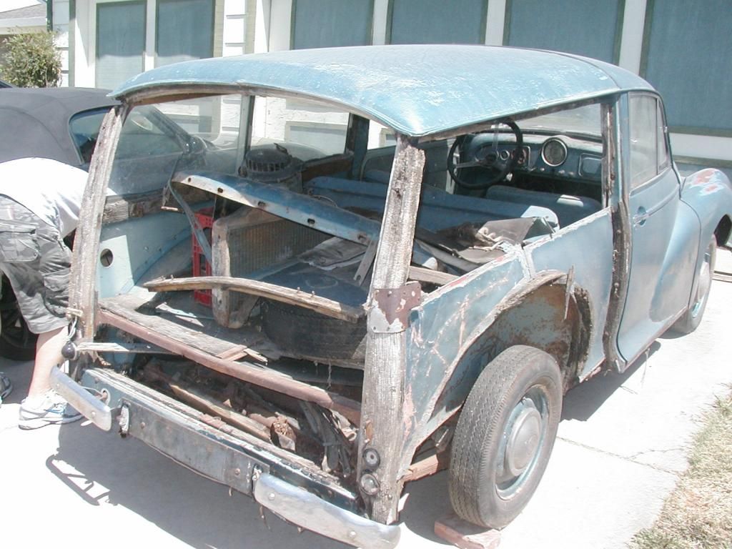
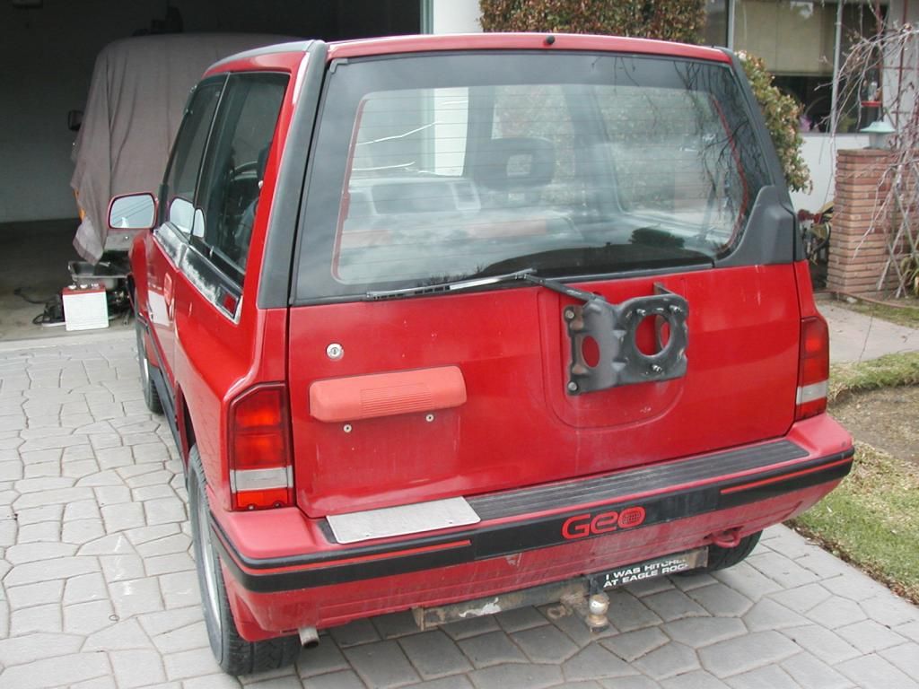
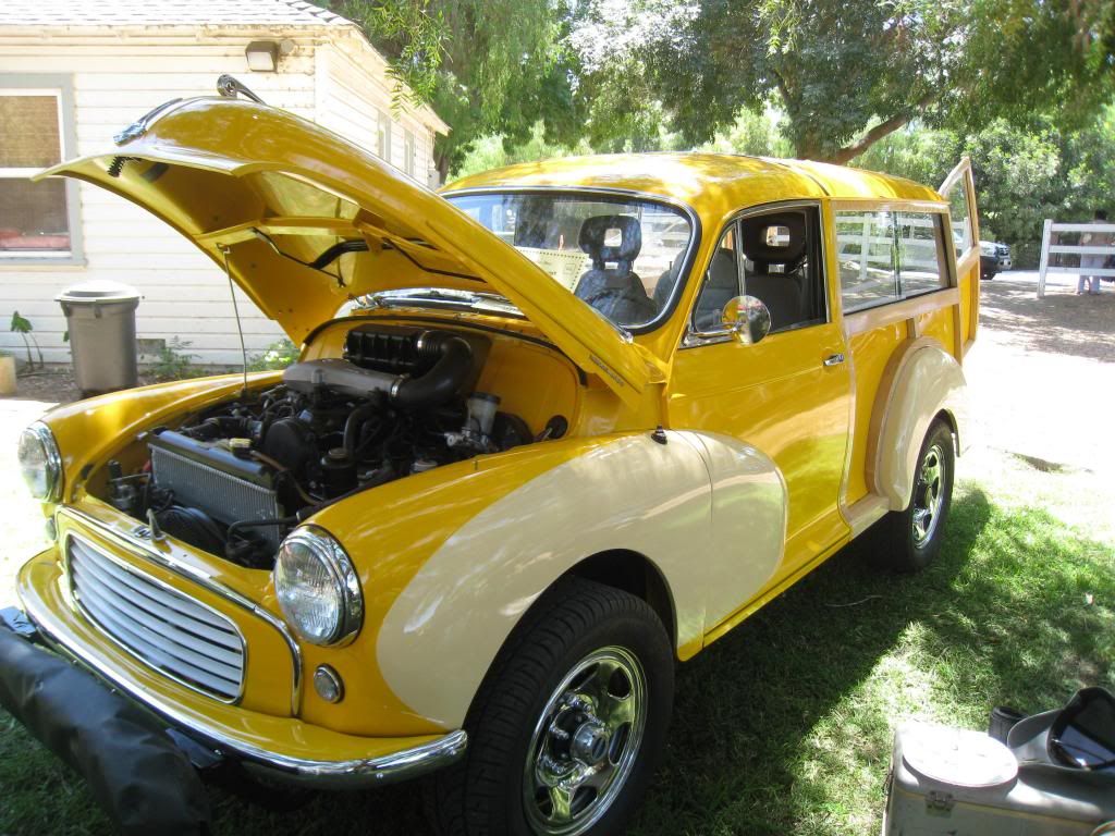
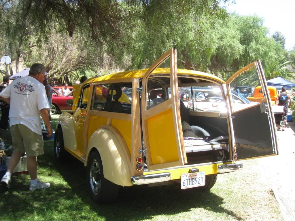
Hello All. Tamangel spotted my Morris Minor Toad for the bus on another post and asked if I had a build thread on it. I don't but I do have a few pics to offer. I chose the 1959 MM woodie wagon as my Toad because I think its lines look a lot like the lines of my bus. Both are round and have tear drop shaped rear fenders etc. While I did get the MM to run well enough to be able to sell the driveline to a MM nut, I wanted something I might actually be able to use on the highway or in the mountains which the stock MM just couldn't do. I ended up with a fuel injected 4X4 Geo Tracker because it clearly had the power to go the distance and just happened to have the same wheel base as the MM (wider though).

Eventually I will paint the bus in the reverse color scheme of the MM (tan body with yellow fenders) thereby making it clear that the bus is not a working school bus. The yellow is actually a Toyota FJ color, not SBY.

I thought the Morris would be a quick fix but it took me a year to finally geterdone --but what fun to drive! Jack

This is the MM as I bought it.Image

The Tracker had accident damage but drove just fine.Image

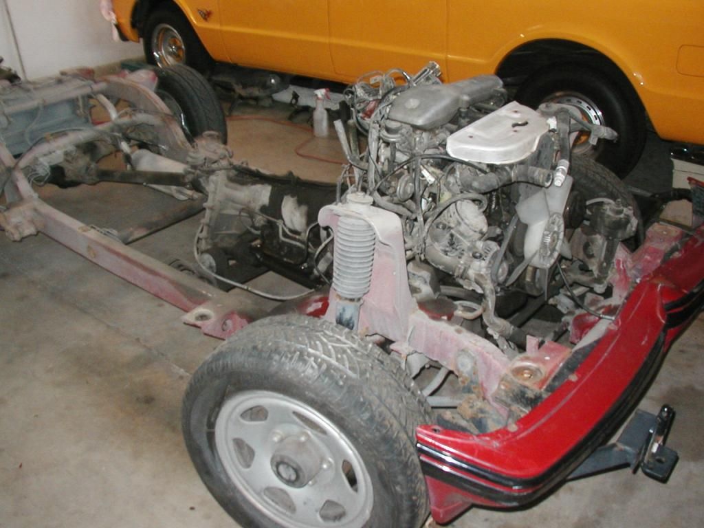
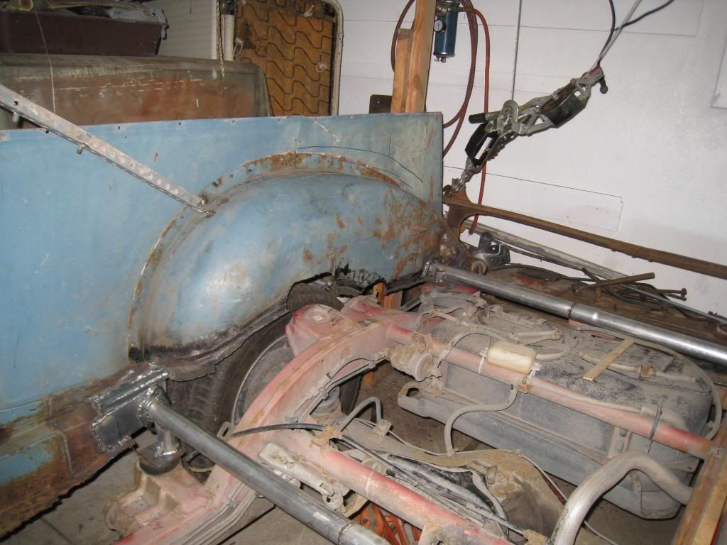
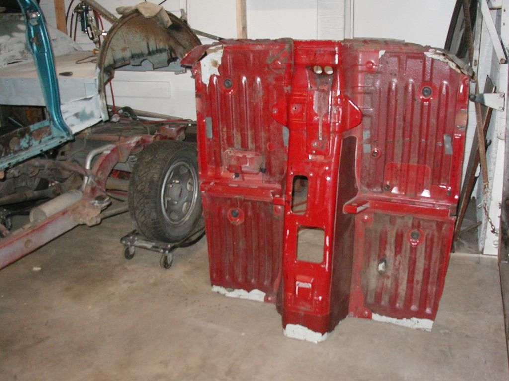
I kept the chassis, drive line, floor pan and interior.Image

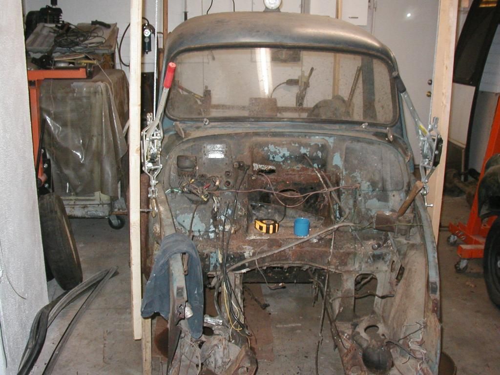
The MM had heavy accident damage to the rear floor area and plenty of rust in the floor --so I cut it out. I hung what was left from the rafters of my garage on come alongs and began work.Image

I built a tube frame for the MM so I could bolt it to the Tracker frame.Image

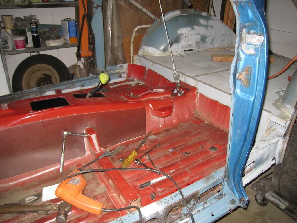
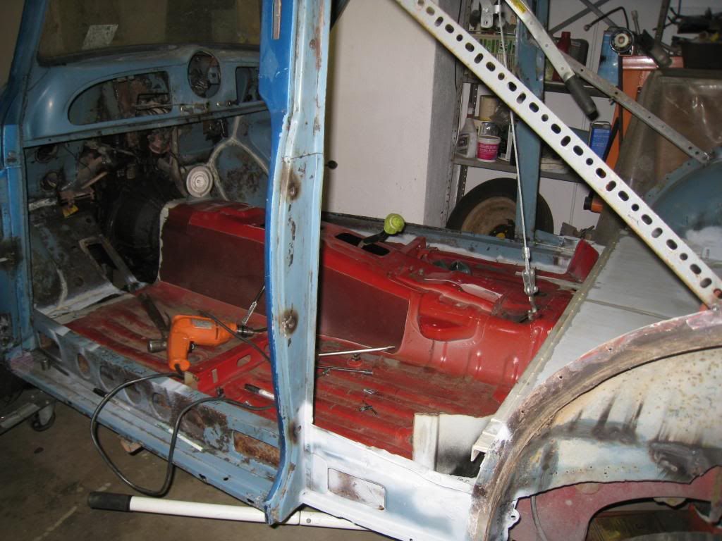
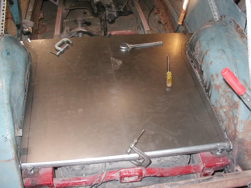
Next I fit the Tracker floor into the MM.Image

Image

Image

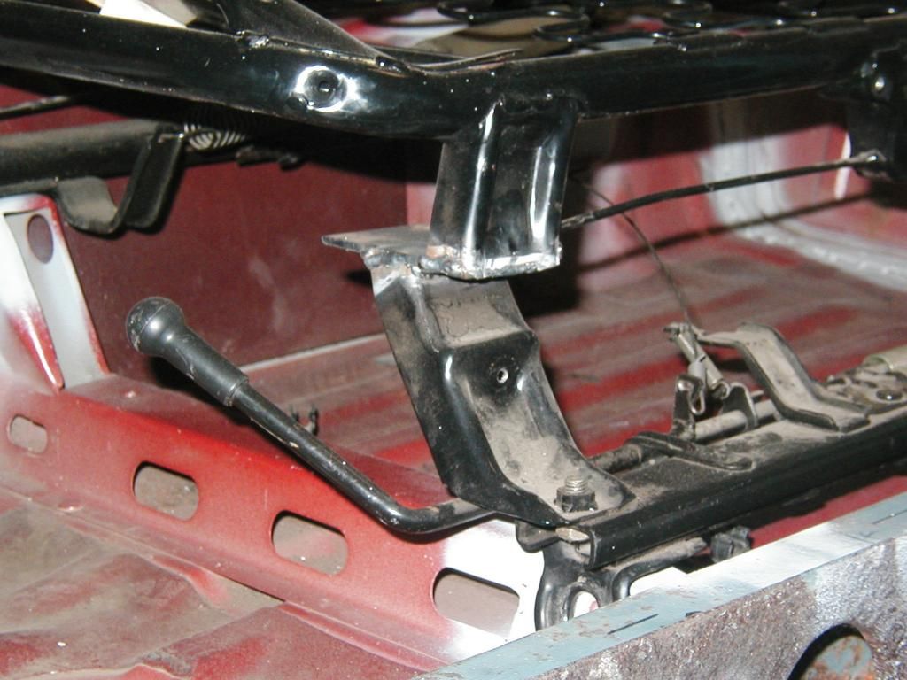
I had to narrow the seat frames to fit the MM.Image

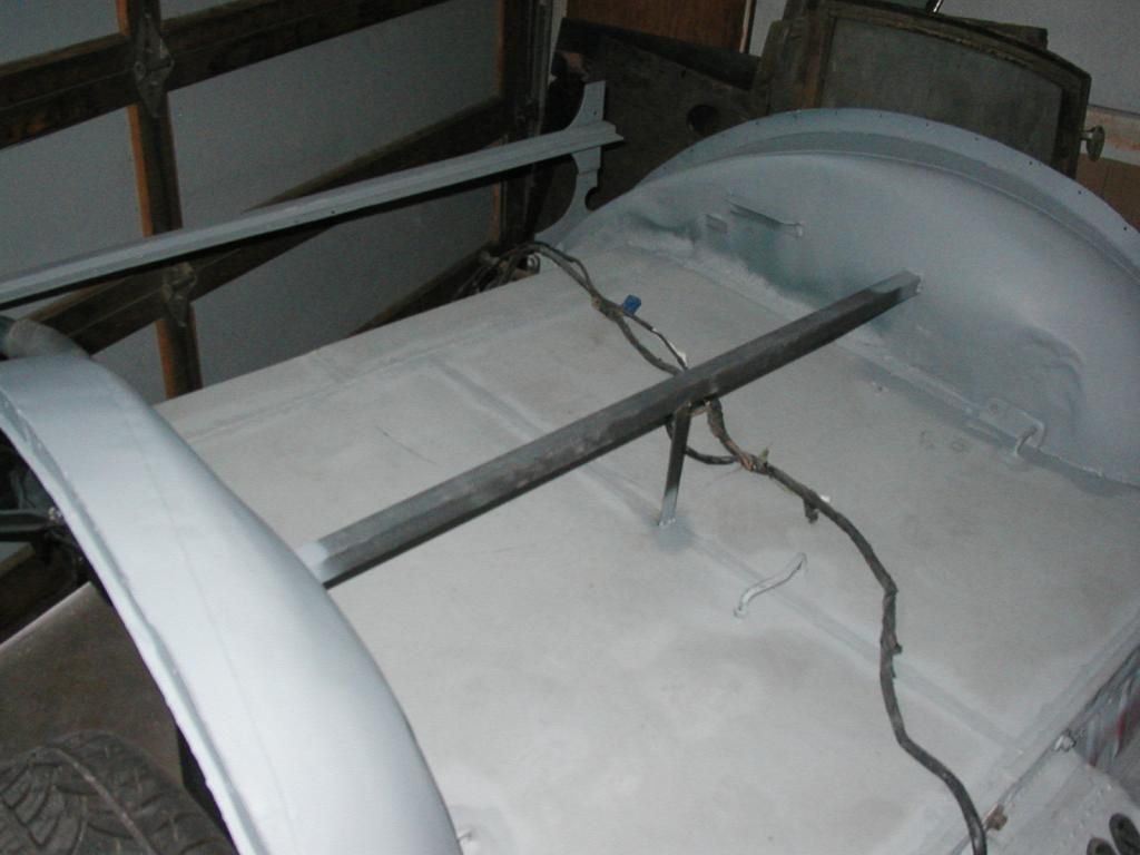
I also made a new replacement rear floor for the MM so it would look "original"Image

Image

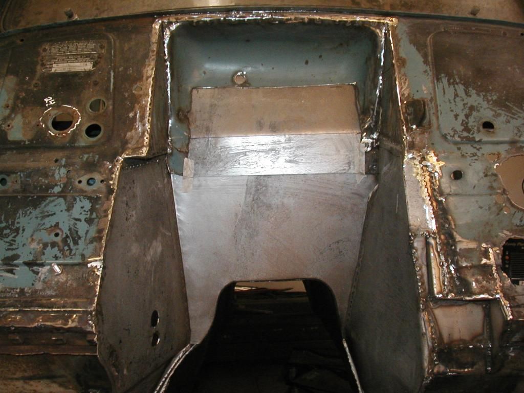
I had to reverse some of the sheet metal on the MM dash and build a new trans hump for the 4X4.v
Image

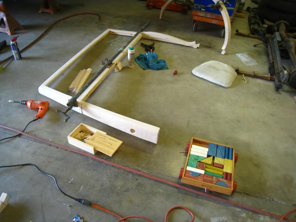
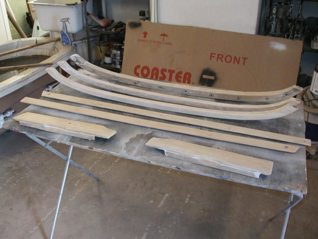
The wood was next. I bought a "kit" from England--nothing more than loose fitting scraps--I sure learned a lot!Image

I was able to restore the interior structural wood.Image

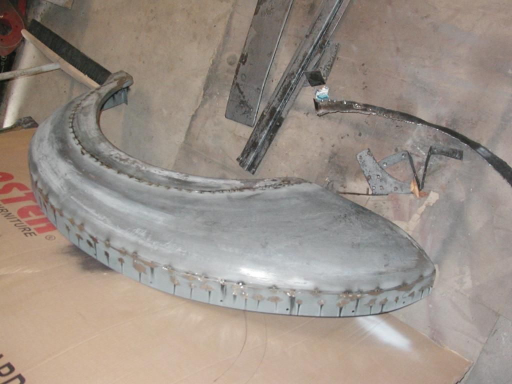
Next came reassembly and paint. The rear fenders didn't look good so I reduced the opening and added 2" width.Image

Image

[b]Image[b]

[b] First show. I've just added the tow bar.ImageImage
Dusty
Posts: 356
Joined: Sat Jan 09, 2010 6:06 am
Location: New Zealand
Contact:

Re: 1935 Chevy school bus

Post by Dusty »

^ ^ ^ ^ ^ ^ AWESOME ^ ^ ^ ^ ^ ^
58 Bedford House
ol trunt
Posts: 551
Joined: Thu Jan 17, 2013 2:51 pm
Location: Southern California
Contact:

Re: 1935 Chevy school bus

Post by ol trunt »

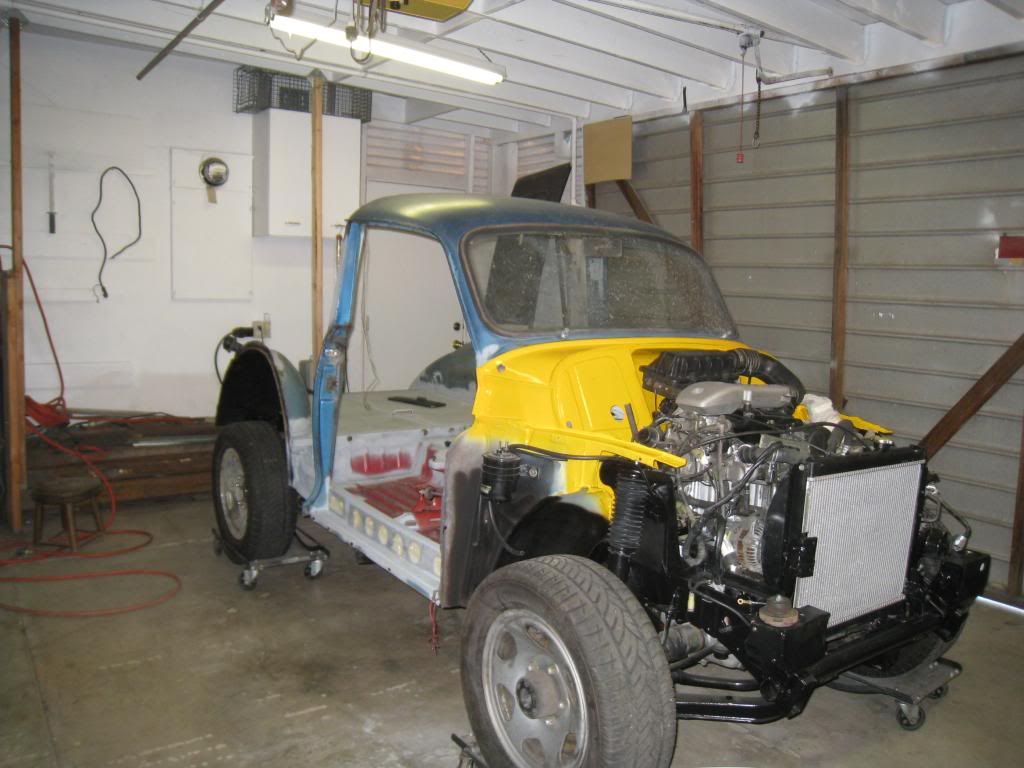
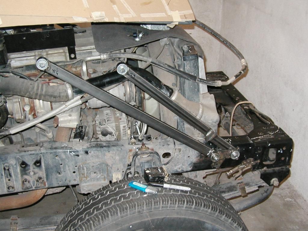
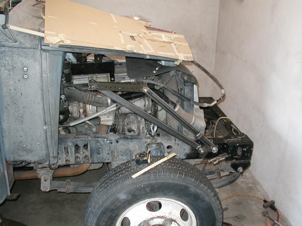
Hello All. I had lots of interuptions over the last couple of weeks so not much to share. I did get the two pairs of hinge arms built. I planed on using a single bearing on each arm where it articulates with the frame but the ball bearings allowed too much lateral movent for that. I used a shaft welded through the arms and supported at each end by a bearing--plenty firm now. Because the hood line narrows from the cowl to the radiaror I was forced to "stair step" the front hinge arms to make them fit under the hood. I attached the paint stick mock up to the arms and they seem to work as expected. I'm still many hours away from test fitting the sheet metal but thats OK as it will give me time to think about things.

I noticed that I'm missing about 15% of my pics (right side). What do I need to do to correct this? Any ideas? Thanks, Jack

This pic shows the hinge arm installed. It took hours to get the various pivot points to match up with their mirror image on the other side of the frame. So far I can only find 1/32" misalignment in one arm, but I know I'll be adding to it as I progress so I'll have to be careful.Image

The green colored angle iron attached to the upper pivot points is a mock up of the hood line and should allow me to figure out the mounts for the front sheet metalImage
User avatar
stuartcnz
Site Admin
Posts: 875
Joined: Fri Dec 19, 2008 8:05 pm
Location: Aotearoa, New Zealand
Contact:

Re: 1935 Chevy school bus

Post by stuartcnz »

ol trunt wrote: I noticed that I'm missing about 15% of my pics (right side). What do I need to do to correct this? Any ideas? Thanks, Jack
The photo's actually are all there, from what I can make out. The issue would appear to be in the image size, which on forums in general should be 640X480 pixels. Due to the way that forum software works, the screen size automatically adjusts for the size of the display on your computer, but the photo's are a fixed size. So when I look at the post with my desktop, with a large screen, I see everything. However, when I view the same post on my laptop, with a much smaller screen, I only see from the left hand side, until I run out of screen real estate, the rest of which is cut off.

So the long and short of it is to resize your photo's to 640X480 pixels either before uploading them, or during, if photobucket allows you to. Alternatively, you could use tinypic.com to host your photo's which does allow resizing, during upload.
ol trunt
Posts: 551
Joined: Thu Jan 17, 2013 2:51 pm
Location: Southern California
Contact:

Re: 1935 Chevy school bus

Post by ol trunt »

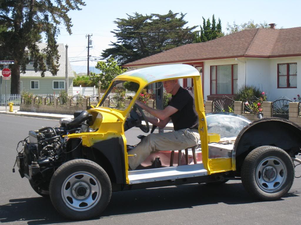
Hello All. I completed the hood hinge mechanism today and welded it up. It moves easily on its 16 roller bearings and exhibits almost no unwanted lateral movement. I clamped the stir stick mock up on the completed hinge and it still works like the model. I knew that some point I was going to need to move the shock towers to accomodate the front sheet metal but I have been putting it off. At this point I could wait no longer--I had to be sure the hood flaps, shock towers and fenders would play nice together before I welded up the hinges. Only took 4 days to figg'r it out and about 30 minutes to weld new braclets on the original towers and I was done :lol: While the original shock tower/shock mount allowed for 12" of travel, I suspect that that was designed in to allow for multiple applications of the tower. In my application the maximum movement of the front axle is only 2.5" stop to stop. I took advantage of that and allowed 3" of travel--just in case. The original shocks are gas charged and even after 39 K miles still pop open if not restrained. As oversize as they are I'll probably never have to change them--guess I'll weld 'em in! just kidding. Jack

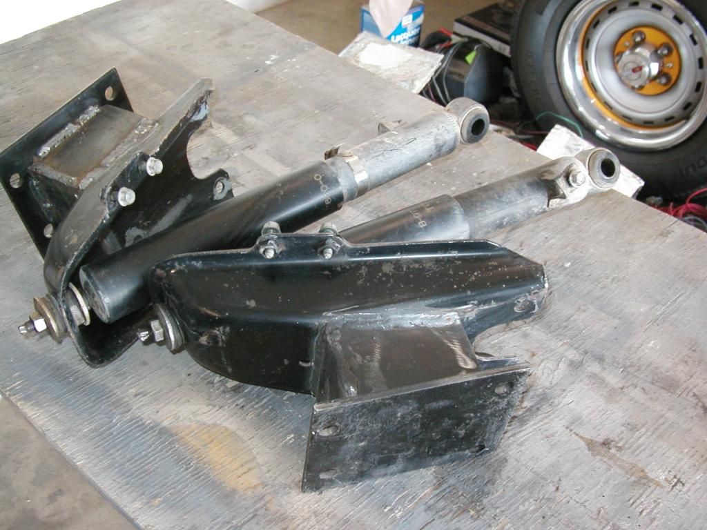
Fortunately I was able to use the factoryframe mounts for the shock towers. I built a "triangular" box that bolts to the original hardware and moves the shocks out laterally and down thereby giving room for the curve of the old fenders.Image

I mounted the tubing that connects the two (L & R) hinges. This in effect welds the two sides together so they "have to" move together.Image

Changing the location of the shocks reouired moving the wiring for the ABS system. After some study I discovered that the left and right side sensors could be exchanged with slight modification to make everything work.Image

More--this time with some tilt.Image
Dusty
Posts: 356
Joined: Sat Jan 09, 2010 6:06 am
Location: New Zealand
Contact:

Re: 1935 Chevy school bus

Post by Dusty »

Its gonna be Another cool feature of the bus :)
58 Bedford House
tango
Posts: 185
Joined: Sun Mar 17, 2013 7:56 am
Contact:

Re: 1935 Chevy school bus

Post by tango »

Hey Jack --- lookin' good! Gonna be one slick front end. Course you could'a gone one step farther and made a complete tilt-cab arrangement all the way back behind the drivers seat but what you've got there is pretty dammed cool. But it does appear that now you may have to knock out the back wall in your garage in order to flip it all the way forward, but hey...I'm sure the wife won't notice.

Rock on!
ol trunt
Posts: 551
Joined: Thu Jan 17, 2013 2:51 pm
Location: Southern California
Contact:

Re: 1935 Chevy school bus

Post by ol trunt »

Hey Tango. You're right about the tilt being in the way. Now I will have to pull the bus out of the garage with all that entails before I can open the hood. I don't think I'd get away with a hole in the garage wall as wiffy has VERY sharp eyes. I'd run out of 3/32 screws to use to temporarly hold the two halves of the hood top together and finally found the one I needed--holding a lamp shade on a light in a never used room--worked perfectly even with the little gold colored thingy on it. Anyway, bright eyes spotted it on the hood and immediately came to the garage with the lamp shade etc. etc! The hood part seems to work ok and I plan to work on a way to attach the fenders to the system. The whole frame is beginning to look like a school yard jungle jim! Jack
tango
Posts: 185
Joined: Sun Mar 17, 2013 7:56 am
Contact:

Re: 1935 Chevy school bus

Post by tango »

Hey Jack --- Wives are like Mothers...they see all, they know all. Maybe if you just nudged the wall enough to clear the hood, then built on a special "girly" room behind it she might go along. Till then, have fun.

And speaking of fun...when do we get to see the plans for the servos, relays, hydraulics, pneumatics, lasers and electrical that will no doubt hoist this beauty at the touch of a button? Or possibly some kind of mind/machine interface? Somehow I can't picture you settling for a simple manual version of activating this contrivance.
ol trunt
Posts: 551
Joined: Thu Jan 17, 2013 2:51 pm
Location: Southern California
Contact:

Re: 1935 Chevy school bus

Post by ol trunt »

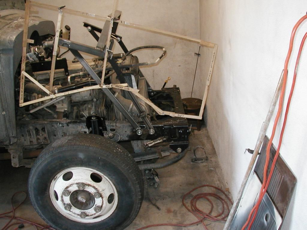
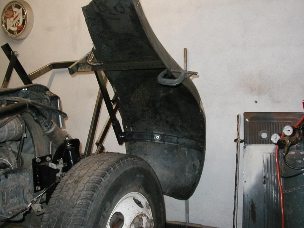
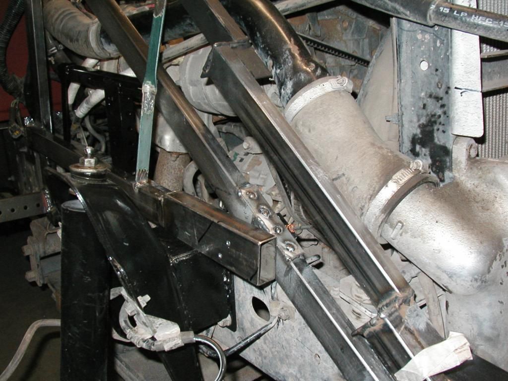
Hello All. Funny how it goes, I've been stewing for weeks about how to attach the fenders to my tilt mechanism and yet when it came right down to it, it seemed simple. I added a couple of rungs to the jungle jim and hacked away at the original fender brace and made a second brace, tac welded the thing together --and it works!?! No blood, no fires--wish I new the secret!

Tango, you beat me to it. I've been "showering" over the lift mechanism and what with the easy day in the shop I fabed up an opener. So far it utilizes a HF (can't say the words--hate the place and the products but keep going back) 2000 # winch (yea sure, I bet they misplaced a decimal point HA!) and a couple of as yet undetermined gas struts. It was way too easy--sumpins wrong. Jack

I've already tried the hood and it works so having the fender also work is great news. Of course it'll take days to get it all to play together but it was a good day.Image
tango
Posts: 185
Joined: Sun Mar 17, 2013 7:56 am
Contact:

Re: 1935 Chevy school bus

Post by tango »

Hey Jack --- Sounds like we have the same formula for estimating the cause of things going too easily...

D= e/1000 squared

"The potential for total disaster is in direct proportion to the ease with which any given task is accomplished times 1,000 times itself."
ol trunt
Posts: 551
Joined: Thu Jan 17, 2013 2:51 pm
Location: Southern California
Contact:

Re: 1935 Chevy school bus

Post by ol trunt »

Hello All. Well, I sidesteped Tango's formula for disaster, but the easy button was only good for one day. What should have been a simple mirror image fender mounting bracket right to left turned out to be hours of design and trial and error because I'd overlooked the fact that there is a large power steering gear attached to the drivers side frame right where the "mirror" brackets were to go.I guess I should have remembered it since I'm the one who repositioned it there--I tend to forget bits of the project once they are in and done and work. Why would I want to clutter my little pea brain with that stuff--it worked didn't it? Ha.

I only got as far as making the bracket to support the small winch I will use to open and close the front end. I had gotten far enough with my mock up to know that the winch would work if I could come up with a way to keep tension on the cable once the hinge arms rotated over top center and headed down towards the road in front of the bus. Once the hinge arms pas TDC, they allow the winch cable to go slack which equals instant bird's nest. I had invisioned hydrolic struts ( like those used to hold up lift gates on minivans), but after hours of research and measuring and looking it became clear struts were not the answer. Struts push and I needed something that would pull. :banghead:

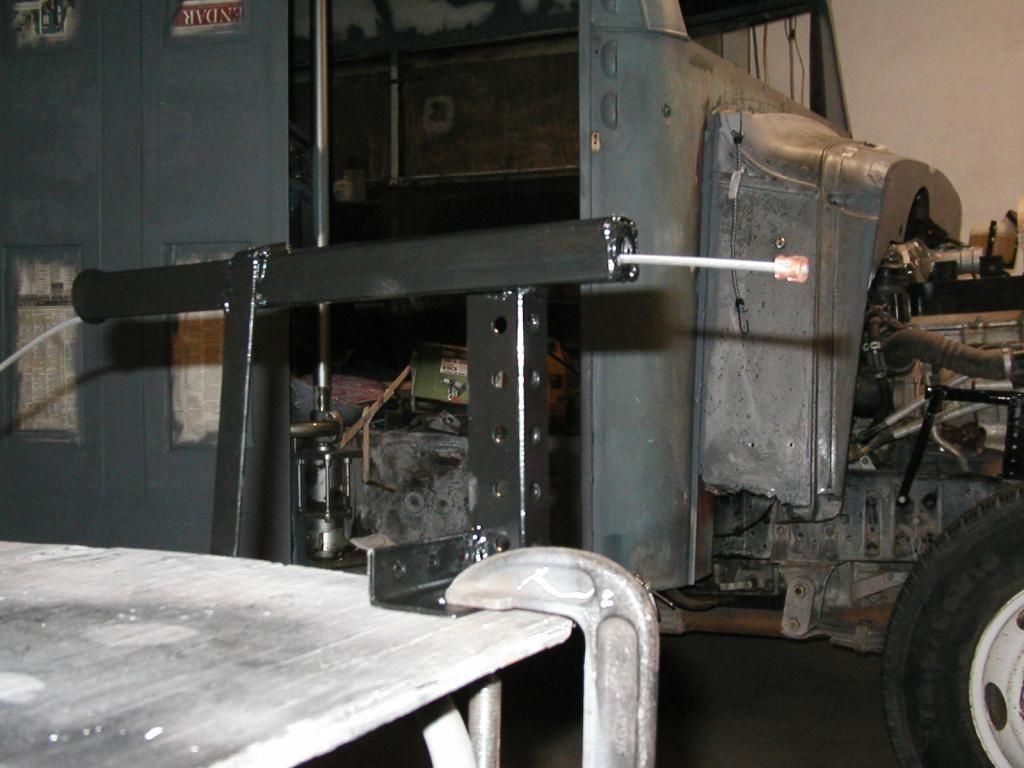
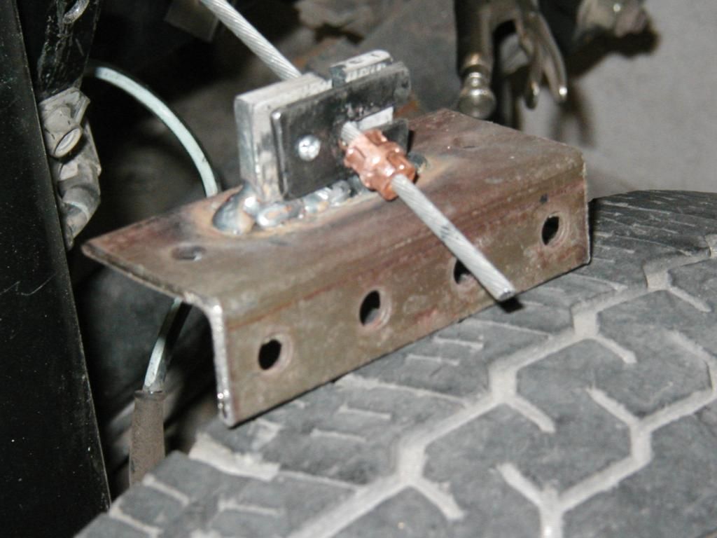
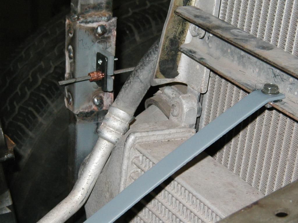
Once I figured out a way, KISS became very clear to me (as it often does in these situations). I stuffed 4 valve springs one on top of the other in a square tube (less friction) and added a piece of brake cable and a couple of mounting brackets and hooked the cable to the hinge arm so that it would provide resistance once the hinge passed TDC. I don't have a valve spring tester so I used the empirical method to come up with an idea how much weight it took to activate/overcome the valve spring tension. I needed 3" of travel and when all was said and done that was provided by 4 valve springs in a row. My first attempt to determine the load the spring would tolerate amounted to me standing on the top of the spring to see if my weight would compress it--ever tried standing on a valve spring? But since "it ain't my first rodeo" I remenbered to tether the spring with a piece of wire so when it got away it would do no damage! My 175# mashed the spring closed so I enlisted the help of the 'ittle engineer (wiffy) and discovered that her 115# didn't compress the spring completely. The bench vice, the spring and the wire and I discovered that the movement of the spring under compression was 3/4"--hence 4 springs. Its an illness I suppose, but I've never been able to leave well enough alone.. I just had to know how much weight it would take to overcome the 4 springs in a mock up. This I acomplished with a length of #10 electrical wire tied to the hood arm pivot point and wrapped around a bathroom scale. It takes 50# to overcome the valve springs 6" from the fulcrom. OK, I wonder what it is up here on the same arm ( about 20" further from the fulcrom)--WHOAH!, I went flying--5# is all I had time to read before I went crashing backwards. No harm done except to my ego thank goodness. I know I'll never learn! Jack

A pic of the tube containing the 4 valve springs (looks like a shoulder rocket launcher doesn't it?). Image

I made keepers to prevent the cable from disengaging when slack.Image

{b] A pic of the device extended.Image[/b]

A pic of device retracted.Image
tango
Posts: 185
Joined: Sun Mar 17, 2013 7:56 am
Contact:

Re: 1935 Chevy school bus

Post by tango »

Jack --- what can I say at this point but "you never cease to amaze! But...we just gotta know...what engine are the valve springs out of...a Pinto or a Hemi?
ol trunt
Posts: 551
Joined: Thu Jan 17, 2013 2:51 pm
Location: Southern California
Contact:

Re: 1935 Chevy school bus

Post by ol trunt »

Hello All. Tango, the valve springs were from a 16 valve 4 cyl Isusu of some ilk--I wanted to keep the bus all Chevy. Ha.

I spent Friday and Saturday helping my friend Jeff who owns a tow company tear apart an '83 Surveyor sticks and stapels. In order to scrap a MH at the local recyclers you must first separate the aluminum, steel and wood or they won't accept it. I did manage to salvage a 3 gpm working water pump and a very nice Magic Chef 4 burner stove/oven with a beautiful black porcelain top and a black glass oven door--way nicer than the rusty stainless steel wanabe I had planed to use. The black water tank was a different story. I'm sure you know the line about the ten pounds of s--- in the five pound sack, well this was fifteen pounds--NASTY, NASTY. At least the jokes were funny and the company good. Neither of us is afraid of a little hard work and a lot of dirt.

Lets see, where was I? I spent today working on the drive mechanism for my tilt hood. I got the winch installed in the first front X menber and then worked my way back to the cowl. The '35 Chevy had a double butterfly hood and I replaced the center hinge with angle iron.. This piece is over 5' long and had I installed it today I would then have to move the bus everytime I wanted to tilt the hood. To avoid that PITA I also bult a short hinge replacement that allows me to open and close the hood without moving the bus--hence all the "C" clamps in the pics.

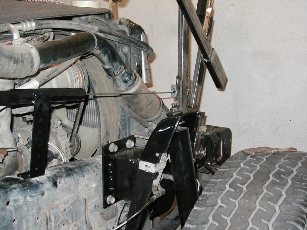
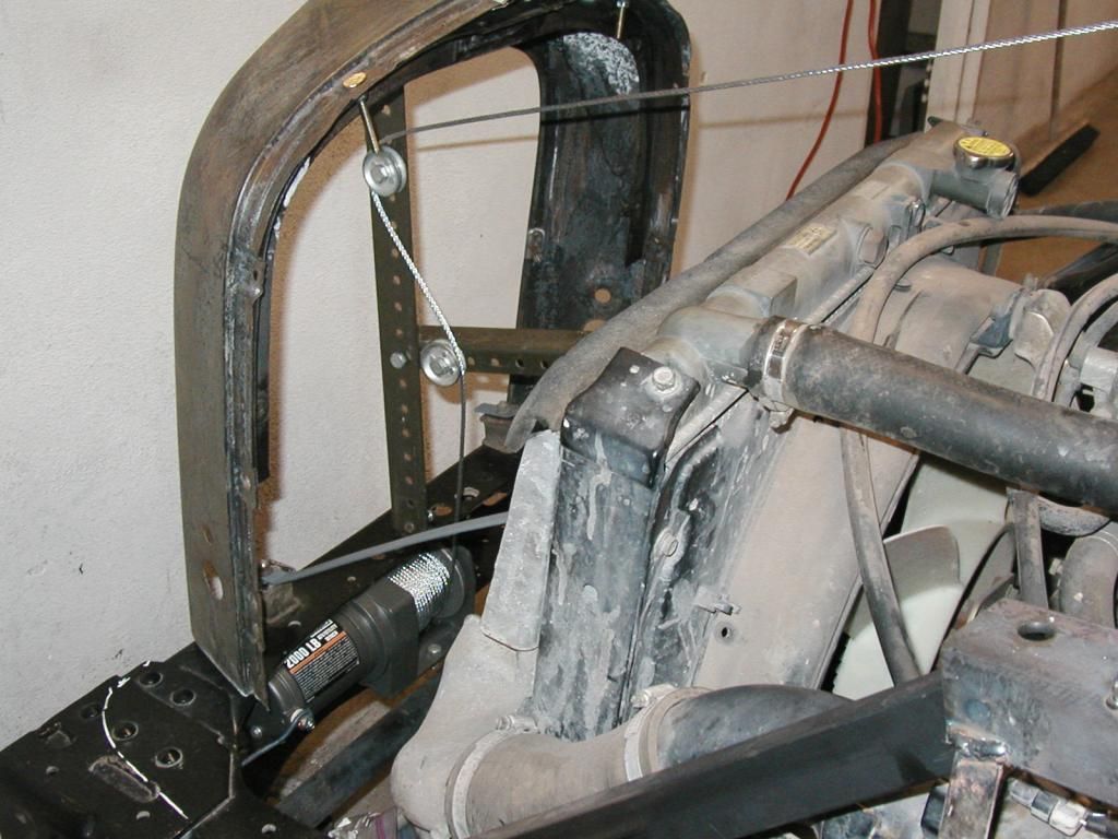
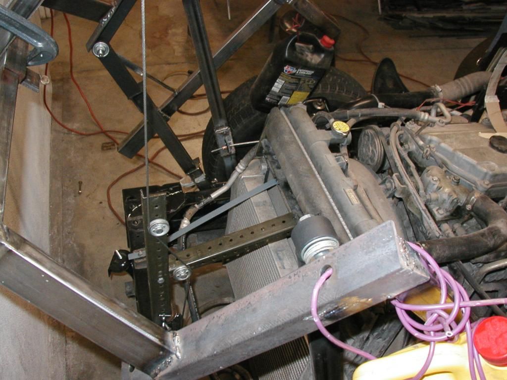
There is a "U" shaped channel that spans the radiator/intercoller which was originally used as the point at which to tether the tilt cab on the Isuzu truck. I chose this point as the fulcrum for the winch driven hood opener. The first time I tried it the radiator pressed back a couple of inches and I was sure I had wrecked something--you know that sinking feeling. It turned out to be no more than movement in a couple of very stout rubber mounts for the radiator/intercooler.. I probably didn't need to do anything but just to be safe I added two more rubber mounts to further help resist the leverage being applied as the hood begins to open. Once the hood starts to move most of the pressure at this point goes away.

The mechanism produces a very macho growl sort of like the sound of a '20's PTO as it opens and closes--but it works. Jack

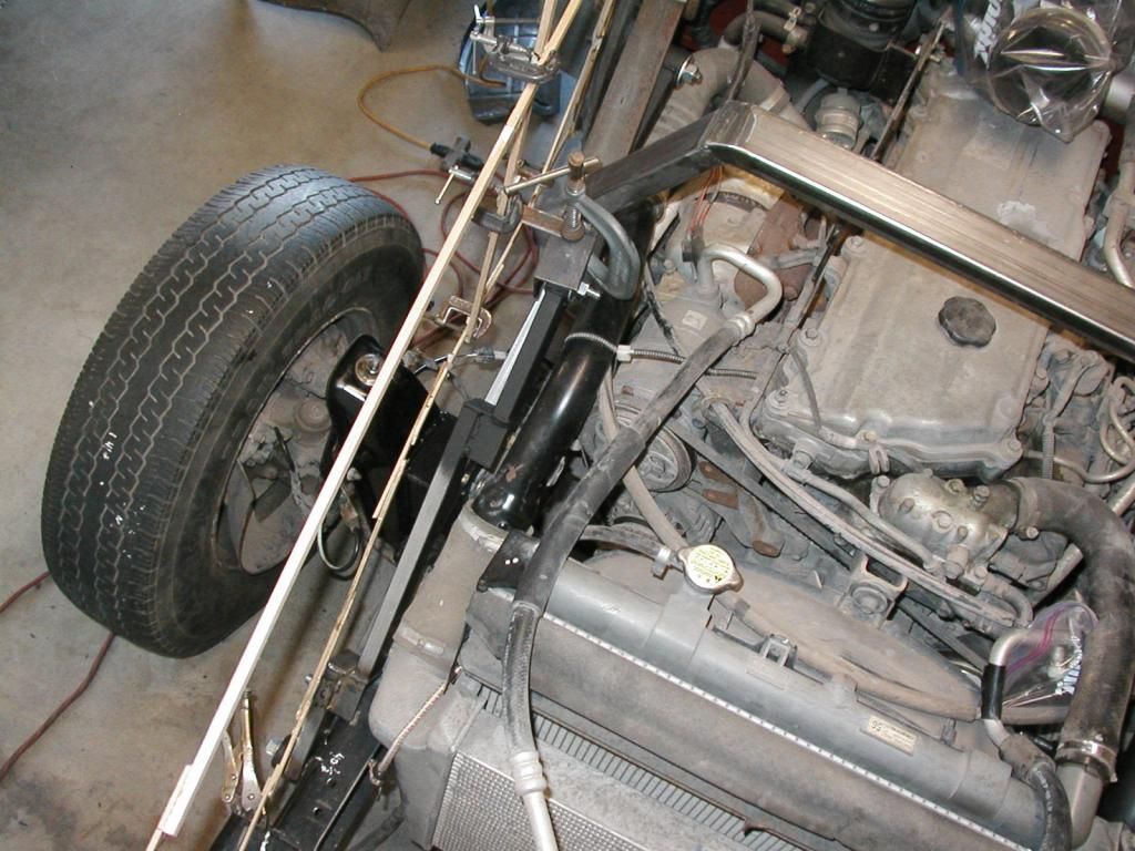
In this pic you can see the winch and two pullies and the additional rubber mounts in the area below the radiator shell.Image

Look for the copper compression fitting. The "rocket launcher" is about to come into play.Image

In this pic the mechanism is fully extended and the cable remains taunt. Way to go Jack! too much fun!Image
User avatar
somewhereinusa
Posts: 323
Joined: Sat Feb 12, 2011 2:44 pm
Location: Andrews, Indiana
Contact:

Re: 1935 Chevy school bus

Post by somewhereinusa »

Jack, as usual good job.You seem to have an inexhaustible supply of large erector set pieces. :lol: I'm always amazed at how much you get done in a short amount of time. The amount of rain we've been having, I have to mow two to three hours a day, just to kind of keep things looking like someone actually lives here. Not sure what size that cable is. If you have TSC stores, or any kind of place that sells high tensile fencing They have crimps that work quite well on cable.
Post Reply

Who is online

Users browsing this forum: No registered users and 27 guests