Bus Living, Truck Living, Boat Living. You name it, if you live in a home that is capable of moving by itself, or have the desire to, then this is the place for you.
Hey guys, i thought i'd do a separate thread for this question.
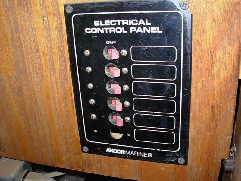
As i mentioned in the other thread i am installing a 12v DC power socket circuit on my housetruck so i can plug in various 12v appliances and run them direct from DC much as you would with an AC domestic circuit using domestic appliances.
My question is regards earthing this circuit as well as all my 12v lighting circuits? Do i need to do this or not? All DC load circuits will draw from the batteries through either an auto electrical blade fuse box or a DC consumer unit with circuit breakers. At what point in my DC system would i earth it? At each socket & light fitting (dont know how i'll do this if im using 2-core flex), at the fuse box/consumer unit or somewhere around the batteries??
Ive read a few things warning against using the chassis as 'earth', as this is likely to bring on galvanic corrosion or other problems?? One solar installer i spoke to on the phone simply told me i dont need to bother with earthing 12v DC at all!?!
Im very confused about this. Would appreciate if anyone can offer any guidance on earthing 12v DC circuits on a RV/motorhome/housetruck.
The term "earthing" generally refers to AC mains circuits.
I am assuming you are somewhere in Great Britain. (your reference to "two-core flex")
In the US we run 240VAC from pole to service panel where it is split into two 120VAC legs to feed the circuit breaker panel in the dwelling.
The 120VAC circuits are run with three conductors, the 120VAC "hot" wire (one half of the 240VAC in-feed) a "neutral" and the "earth" or "ground" wire. The ground circuit is actually attached to a rod stuck in the ground (or earth).
The ground circuit is a redundant neutral circuit. If the neutral should open any current in the circuit will travel through the "ground" circuit to ground, rather than through you.
Another reason is lightning protection. It is believed that an over voltage/surge from a lightning strike would be safely conducted to earth.
Your concerns are with 12VDC or low voltage circuits which require only two conductors. A positive and a negative conductor.
Since you are running two-core flex, which I also assume is stranded two conductor cable, you will not require an "earth" in these circuits.
One concern is proper wire gauge (conductor diameter) for adequate load handling.
Overload protection in the form of fuses or circuit breakers is necessary.
I hope this answers you concerns.
Bill
Things are more like they are now, than they ever have been.
Wow! Nice Crown Dan. I'll have to know what engine, tranny, how long, what year? Mine's a '78 35' with a Detroit and Fuller 5 speed.
Nice images very helpful.
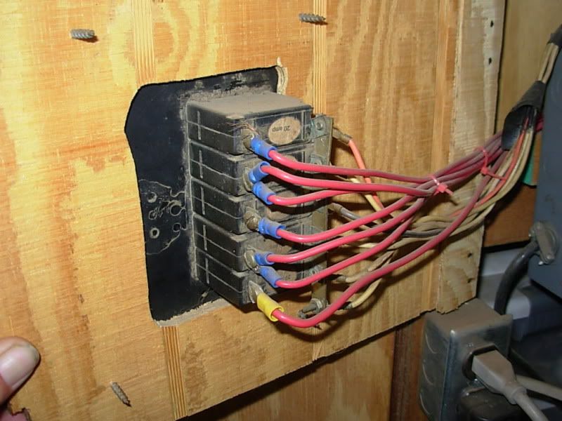
In the view of the back side of the breaker panel there is a buss bar connecting all the breakers together. On the opposite end of each breaker a single red wire is attached.
There actually should be only one wire attached to the buss bar end. This is the supply or "line" side of the breaker. The single red wire on the other end of each breaker is the circuit feed or "load" and is the protected end of the breaker. The load end looks OK.
A red wire coming from a master fuse or battery switch connected to the positive terminal of the battery should be all that is connected to the buss on the "line" side of the breakers.
Often the buss bar is used as a tie point to pick up 12VDC for "add on" circuits. Unless designed into the system this can overload the wire feeding the breaker buss and cause voltage drop or worse.
The gauge of the feed or "line" side wire should be a minimum of 4 ga. if not 2 ga. for the loads you described earlier. A 2 ga. cable may seem large but if you decide to upgrade to more circuits later on you'll be ahead of the game.
Are you picking up your twelve volts from the buses battery switch in the passenger side engine compartment? On my crown there is a 100 amp barrel type master fuse just after the battery switch for the "house" power. It is located just under the floor on the aft end of the pass. side engine bay. This would be a good place to pick up your 12VDC feed for your panel.
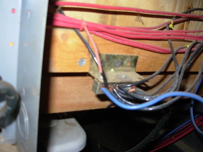
The ground cable must be the same gauge as the positive cable and could be bolted to the engine block and the other end terminated at the negative buss bar in your image.
This neg. buss should really be mounted on a piece of heavy plastic or rubber to insulate it from the wooden bulkhead.
Cole Hersee makes a very nice buss that is a copper plate ~ 1/8"X1"X 4" with six or seven copper machine screws staggered in two rows mounted on a piece of high dielectric plastic with 1/4-20 studs and nuts. You could make one or find one used at a boat yard possibly.
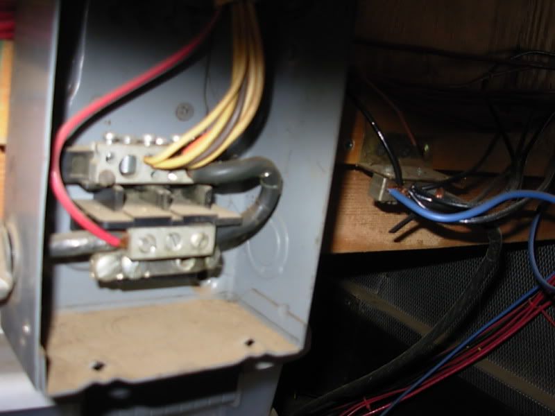
There is a blurry image of a gray junction box with a heavy gauge black wire and several smaller gauge yellow, brown, orange and one red wires.
This may be 120VAC be careful!
I hope I'm making some sense here.
It's past my bedtime so I'll pick this up later.
CU, Bill
Things are more like they are now, than they ever have been.
To keep the breakers, which are mounted on a door flexible, I ran several hot wires to the buss bar. The power comes from 6 deep cycle golf cart batterys. 6 volt batterys wired for 12 volt. The bus bar in the last photo is a common ground direct from the battery pack. The feed from the battery to the junction just before the breakers a 00 wire I think. Its as big as a triple AAA battery is.
The negative buss is never going to short out being hooked to wood. Maybe with 120 volts, but not 12 VDC and being the ground.
The blurry pic is also 12 volts. Just used some odd ball flexible wire going from the main 12 VDC buss to the breakers, again to keep the flex for the door.
The 120 VAC system is completely separate from the 12 VDC system. And its a tad more on the code side of wiring.
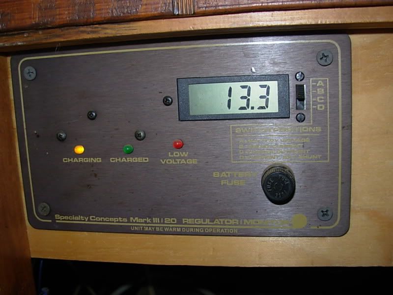
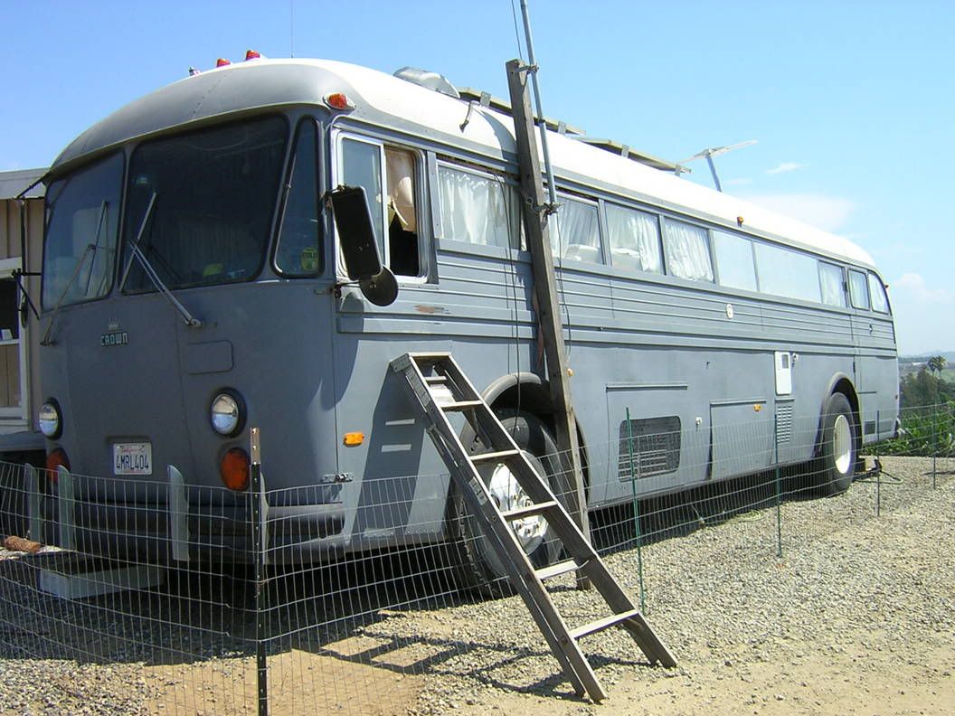
Its a 1965 Crown with the 220 cummins. 5 speed standard. I have 4, 65 watt uni-solar panels on the roof. Charges at around 14 amps at high noon.
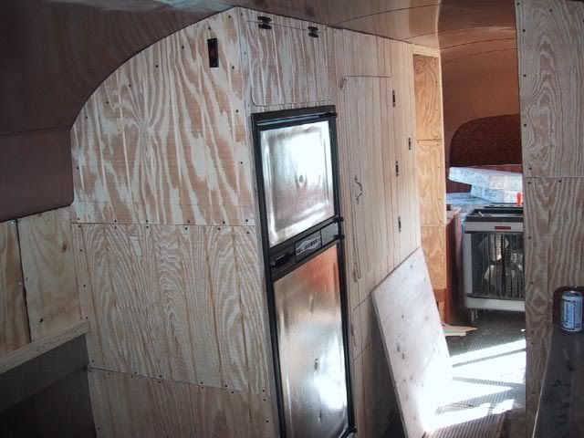
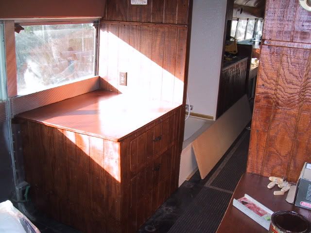
Looks like a comfortable layout. You are a lot farther along than I am. A lot of work.
Thanks for the clarification on the circuitry pics. You apparently have it under control.
You should, however, consider the fact that you have enough energy stored in your house battery bank to burn a hole in 1/2" steel plate.
Sharkey has some good information on this site. Click on "Site Map" to the left of this page and scroll down about halfway. You'll find a file named "Electrics/". Read through these, there is a lot of good info there.
The battery bank should have a means of disconnect from any and all circuits, a fuse and or battery switch, AT the battery bank. For protection against fire or explosion in the case of a major short circuit.
If you plan on doing any traveling with the Crown all those wiring connections are going to experience vibration and shock loading.
My Crown rides remarkably well but it doesn't have air bag suspension.
Make sure all your wire runs are well supported, especially where they terminate.
Copper wire work hardens as it flexes (even a little) becoming brittle and inflexible. It'll break.
My experience, after 20 years of affecting mechanical/electrical repairs to sailing and motor yachts, is that a termination made with an eyelet type crimp connector held in place by a pan head machine screw on an appropriate terminal block is, for the money, about as safe and secure a connection as is possible.
The neutral in an AC circuit is the same as the ground in a DC circuit only in the fact that it completes the circuit.
Alternating current (AC) and direct current (DC) have different characteristics.
Current flow in a circuit supplied by a battery is from the negative post of the battery, through the circuit, returning to the positive post of the battery. Electrons have a negative charge.
Good luck with this great project, and have fun with it.
Bill
Things are more like they are now, than they ever have been.
Sorry HOGCAT, I failed to recognize that your posts were independent of HoFFdOg. So I'll say nice Crown Gary. I guessed, the way you posted, you were working on the same project as HoFFdOg. I'll get the hang of this forum stuff eventually.
Bill
Things are more like they are now, than they ever have been.