I've been working on a design for this controller in my spare time for the last couple of weeks. It's based on the LM3524 PWM voltage regulator chip. My application is a replacement controller for my E-20 Electrak, which uses contactors and series resistance to control motor speed. The output stages of the new controller will be the MOSFET stack salvaged out of an ancient Heart Interface DC-to-AC inverter.
Recently, a topic thread appeared in the DIY Electric Car forum using the LM3524 chipset. The user lazzer408 has done some decent research on using the chip to build a basic controller, but I have some reservations about parts of his design. Rather than contradict him over there, I'll use this thread to refine my own findings, and allow others to throw in their ideas as well.
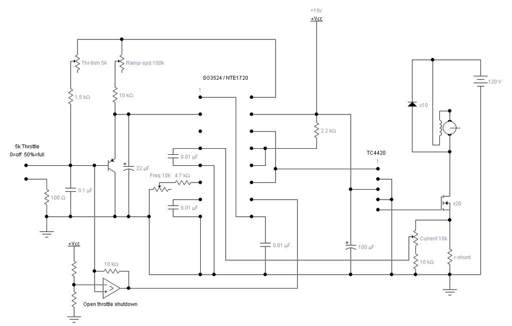
First, and because I haven't had time to draw up a postable drawing of my own circuit, here's the schematic from the first page of posts at DIY:
I'll begin by critiquing one part of the circuit, and add more as I have time.
The circuit, as shown, connects the throttle pot signal to the input fo the error amplifier, pin 2. Pin 1 of the error amplifier is connected to pin 9, the compensation output. This arrangement produces unity gain in the EA, and is probably acceptable.
In my own design experiments, I simply bypassed the error amplifier entirely, grounding both the inverting and non-inverting inputs, pins 1 & 2. The purpose of the EA is to detect and amplify a proportional signal fom the output of the circuit to provide feedback to correct for variances in the operation of the circuit's supply or load. For example, in voltage regulator duty, the chip has to be able to sense the output voltage and adjust the PWM signal to keep it constant. Forcing the EA to unity gain means that it isn't amplifying, so all it's doing is buffering the signal. You don't lose anything by using it, but you don't gain anything, either.
The National Semiconductor LM3524 data sheet has this to say about the error amplifier:
When a manufacturer gives me a shortcut to circuit design, I'm usually inclined to use it.The output of the error amplifier, or input to the pulse width modulator, can be overridden easily as its output impedance is very high (ZO 5 MO). For this reason a DC voltage can be applied to pin 9 which will override the error amplifier and force a particular duty cycle to the outputs. An example of this could be a non-regulating motor speed control where a variable voltage was applied to pin 9 to control motor speed.
My own experiments show that using the compensation pin as a throttle input works quite well, and the shutdown and current limit inputs still work as designed.
That's about it for now. It's a beautiful, sunny day, and I want to go out and get some of it. I'll post some photos of my MOSFET array and expound on other aspects of the circuit in later posts.

